Wednesday 11 January, 2017  Expand to read article below Expand to read article belowThe Prime8 has gone through a redesign to make it better than before! The Prime8 production programmer is a gang programmer than can program 8 PIC® MCUs simultaneously. It can operate via software control over a USB connection, or it can operate without a PC by storing files inside its memory.
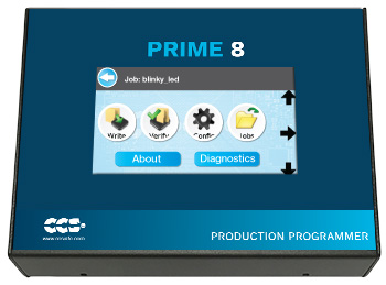
The most impressive update is a touch screen LCD, featuring a much simpler and easy to use user interface. This new UI makes it easy to choose a file and program a file, as well as making it easier to configure the unit. The UI has also been upgraded to show more information about the files stored in its memory.
The speed at which PIC® MCUs can be programmed are also improved. For instance, programming a full PIC24EP256GP206 results in almost 75% reduction in time when using the new Prime8 versus the older models.
The internal memory has been upgraded to 8 megabytes, allowing the user to store eight 1 megabyte files (an improvement over the 2 megabytes and four files of the older models). If a file is larger than 1 megabyte, it can still be stored by using multiple slots of the Prime 8's internal memory. If 8 megabytes of memory isn't enough, it can be expanded using a USB thumb drive connected to the Prime8.
Available Now! Visit: http://www.ccsinfo.com/product_info.php?products_id=P8_gang
Like us on Facebook. Follow us on Twitter.
About CCS:
CCS is a leading worldwide supplier of embedded software development tools that enable companies to develop premium products based on Microchip PIC® MCU and dsPIC® DSC devices. Complete proven tool chains from CCS include a code optimizing C compiler, application specific hardware platforms and software development kits. CCS' products accelerate development of energy saving industrial automation, wireless and wired communication, automotive, medical device and consumer product applications. Established in 1992, CCS is a Microchip Premier 3rd Party Partner. For more information, please visit http://www.ccsinfo.com.
PIC® MCU, MPLAB® IDE, MPLAB® ICD2, MPLAB® ICD3 and dsPIC® are registered trademarks of Microchip Technology Inc. in the U.S. and other countries. | Wednesday 11 January, 2017  Expand to read article below Expand to read article belowCCS has a new software package, Interface Designer, available as part of the IDE compilers. Now users are able to create elaborate Graphical User Interfaces (GUI) with the aid of Interface Designer's user friendly interface. The innovative program eliminates the need to create a GUI entirely from developing C code by allowing users to create a GUI visually within Interface Designer itself.
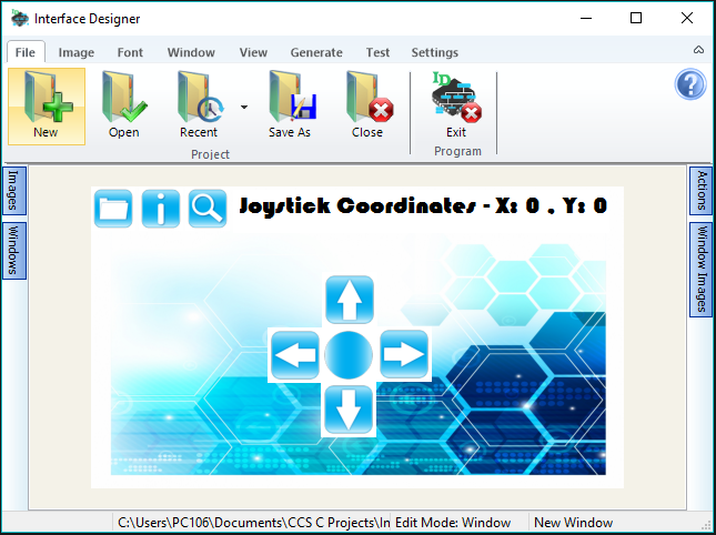
Interface Designer brings user friendly up a notch with its easy to use interface.
- Import custom images or chose from the library of images for use with your GUI.
- Effortlessly create buttons and text boxes with Areas. (A coordinate defined location that registers user touches on the touch screen)
- Implement as many different screens to be used as desired with any amount of Images using Windows, containers that visually display on the touch screen.
- Add Actions allows the defined Area to execute when touched on the touch screen.
- Generate the appropriate C code with one click of a button.
Interface Designer has been designed around the new Touch Display development board developed by CCS. Find the Development Kits or LCD Board here: http://www.ccsinfo.com/product_info.php?products_id=touch-kit
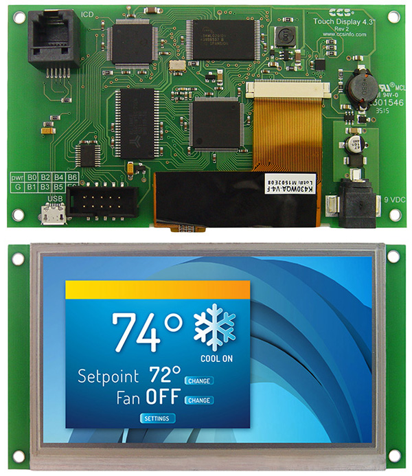
This new development board includes a 4.3" resistive touchscreen with a 480x272 screen resolution and all the hardware necessary to run the most innovative of GUI's. With all the components situated on one development board, the Touch Display gets rid of the typical need to connect a separate microcontroller to an external touch screen display, saving space.
CCS has designed a signature kit for the use of the Touch Display development board which includes all of the necessary hardware and software for successful developing and has included Interface Designer as part of the CCS C Compiler.
Like us on Facebook. Follow us on Twitter.
About CCS:
CCS is a leading worldwide supplier of embedded software development tools that enable companies to develop premium products based on Microchip PIC ® MCU and dsPIC ® DSC devices. Complete proven tool chains from CCS include a code optimizing C compiler, application specific hardware platforms and software development kits. CCS' products accelerate development of energy saving industrial automation, wireless and wired communication, automotive, medical device and consumer product applications. Established in 1992, CCS is a Microchip Premier 3rd Party Partner. For more information, please visit http://www.ccsinfo.com.
PIC ® MCU, MPLAB ® IDE, MPLAB ® ICD2, MPLAB ® ICD3 and dsPIC ® are registered trademarks of Microchip Technology Inc. in the U.S. and other countries. | Thursday 06 April, 2017  Expand to read article below Expand to read article belowSerializing devices in a production environment is simple and easy using the CCS C Compiler and the Prime8 Production Programmer. The CCS C Compiler allows for setting up serialization using the #serialize preprocessor directive. A serial number can be saved in binary or as a string, and can be stored in ROM or EEPROM if available.
This example shows a simple way to store a 32-bit binary serial number (4 bytes) in either EEPROM or ROM. The target device has 256 bytes of EEPROM and 32Kbytes of flash program memory, where the serial number is stored in the last 4 bytes of either depending on the defined location. The #ORG in the ROM variant is to reserve the program memory containing the serial number from being used elsewhere by the compiler.
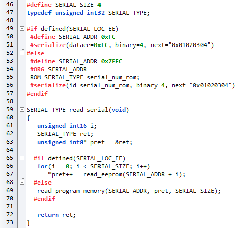
Reading a binary serial number from memory is as simple as reading the raw data directly into a variable using a byte-pointer to that variable. In the example, a pointer is created to a 32-bit variable, which is used to index the raw data bytes. The result is the 32-bit number set by the programmer.
The serialization settings, or "burntime" settings, are saved in the hex file on compilation and are loaded into the Prime8's internal memory when writing the hex file to it. The initial serial number can then be set or changed on the job configuration screen.
Serial numbers are automatically incremented after each successful write, so each connected target will have a different serial number written to it.
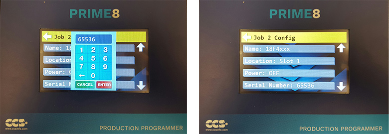
To change the current serial number on the Prime8, select the Config button for the current job. On the Config screen, the file can be selected by touching the "Name/Location" setting, choosing "Internal Memory", and selecting the memory slot the file was written to. This will then show the file name and location on the Config screen. Touch the down arrow until the "Serial Number" setting is visible. Touch this setting to open a keypad where a new serial number can be entered. Once the number is entered, Press the Enter button to save the setting.

Now when the program is written to the targets, the serial number that was entered will be the first serial number written (in this case, 65536), and each successive target will have an incremented serial number (65537, 65538, ...). The number can always be changed or reset by changing the setting again under the job configuration screen.
Prime8 Production Programmer, visit: http://www.ccsinfo.com/product_info.php?products_id=P8_gang
CCS C Compilers, visit: http://www.ccsinfo.com/content.php?page=compilers
Like us on Facebook. Follow us on Twitter.
About CCS:
CCS is a leading worldwide supplier of embedded software development tools that enable companies to develop premium products based on Microchip PIC® MCU and dsPIC® DSC devices. Complete proven tool chains from CCS include a code optimizing C compiler, application specific hardware platforms and software development kits. CCS' products accelerate development of energy saving industrial automation, wireless and wired communication, automotive, medical device and consumer product applications. Established in 1992, CCS is a Microchip Premier 3rd Party Partner. For more information, please visit http://www.ccsinfo.com.
PIC® MCU, MPLAB® IDE, MPLAB® ICD2, MPLAB® ICD3 and dsPIC® are registered trademarks of Microchip Technology Inc. in the U.S. and other countries. | Thursday 06 April, 2017  Expand to read article below Expand to read article belowThe EZ App Lynx compiler libraries, Android Application, and iOS Application have all been updated to to version 3.0! This version includes three new field types to be used in the app.
The first new addition is the Image field. This allows the app to load images from the web or use some of the already preloaded images in the application bundle. Images loaded from the web are cached on the device so they only need to be downloaded the first time a connection is made. Image fields can be used to display plain images, or the images can be used as buttons. Button images can be one-state or two-state buttons acting similar to the normal button fields. These fields allow two separate images to be loaded, where the first is the "on"/"pressed" state and the second is the "off"/"unpressed" state. If only one image is specified, the image field uses the same image for both states. See EZApp.h and ex_ezapp_images.c included with the current CCS C compiler for more info on how to use the Image fields.

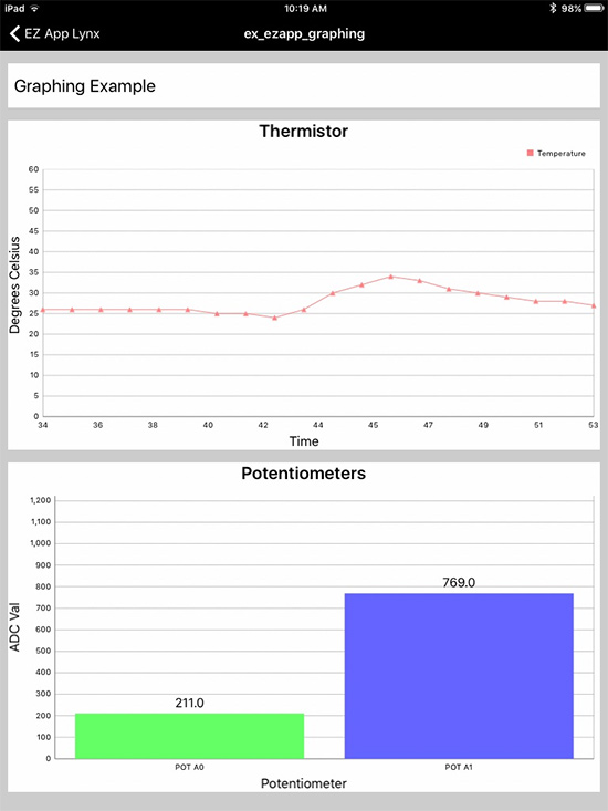
The remaining two new fields are the Graph and Series field types. Together these allow for adding bar graphs and line graphs to the application. The Graph field sets up the graph type, grid lines, labels, data ranges, etc., while the Series field sets up how the data will look on the graph, including color, line type, and series name. Multiple Series fields can be tied to one Graph field, allowing for multiple data sets to be shown on the same graph. See EZApp.h and ex_ezapp_graphing.c included with the current CCS C compiler for more info on how to use the Graph and Series fields.
More information about EZ App Lynx, visit: http://www.ccsinfo.com/content.php?page=ez-app
Like us on Facebook. Follow us on Twitter.
About CCS:
CCS is a leading worldwide supplier of embedded software development tools that enable companies to develop premium products based on Microchip PIC ® MCU and dsPIC ® DSC devices. Complete proven tool chains from CCS include a code optimizing C compiler, application specific hardware platforms and software development kits. CCS' products accelerate development of energy saving industrial automation, wireless and wired communication, automotive, medical device and consumer product applications. Established in 1992, CCS is a Microchip Premier 3rd Party Partner. For more information, please visit http://www.ccsinfo.com.
PIC ® MCU, MPLAB ® IDE, MPLAB ® ICD2, MPLAB ® ICD3 and dsPIC ® are registered trademarks of Microchip Technology Inc. in the U.S. and other countries. | Friday 26 May, 2017  Expand to read article below Expand to read article belowReliably sending data between two devices usually involves a checksum. Creating a checksum of data is a great way to detect if data has be successfully received; by comparing a received checksum to a mathematically determined checksum it can be determined if the data was sent and received properly. A common and easy method of performing a checksum is just summing or XORing all the bytes in the data. Unfortunately this method does accurately detect situations where data may have been received correctly. For example, the result of 0 XOR 0 is still 0. That means a checksum based on XOR would couldn't tell the difference between 0x0000 or 0x00.
The Cyclic Redundancy Check (CRC) is a more robust method for hashing data. In reference to the previous example, the CRC of 0x0000 isn't 0x00. Many new PIC® MCUs released today include a CRC module that perform this algorithm quickly in hardware, and CCS provides a library for accessing this module.
There are two basic versions of the CRC module that some Microchip PIC® MCUs have, a 16-bit module and a 32-bit module. The following getenv() statement can be used in the CCS C Compiler to determine if the device has a CRC module:
getenv("CRC") //will return 1 if it device has a HW CRC module
Both version of the CRC module has a programmable polynomial CRC equation, for the 16-bit modules the polynomial can be up to 16 bits wide and for the 32-bit modules the polynomial can be up to 32 bits wide. The setup_crc() function can be used in the CCS C Compiler for setting up the CRC polynomial. For example the following will setup the CRC module to generate a checksum using the CRC-16 CCITT polynomial, x^16 + x^12 + X^5 + 1:
setup_crc(16, 12, 5, 0);
To calculate the CRC checksum the CCS C Compiler supplies the following functions, crc_calc8(), crc_calc16 and crc_calc32(), for devices with a 32-bit CRC module only. The function that should be used depends on the polynomial size that was set with the setup_crc() function. For polynomials that are 8-bits or less the crc_calc8() function should be used, for polynomials that are greater then 8-bits and 16-bits or less the crc_calc16() function should be used and for polynomials that are greater then 16-bits and 32-bits or less the crc_calc32() function should be used. Additionally the crc_calc8(), crc_calc16() and crc_calc32() have an optional parameter that allows setting the width of the data that the CRC checksum is being calculated for, the data width defaults to the width the function, 8-bits for crc_calc8(), 16-bits for crc_calc16() and 32-bits for crc_calc32(). Finally the CCS C Compiler supplies that crc_init() function that is used to set the initialization value of the CRC generator. This function should be called before every call to one of the CRC calculation function to guarantee correct results.
The following is an example of using the CRC module to generate a 16-bit CRC for some 8-bit data that will be transmitted with the UART peripheral:
#use rs232(UART1, baud=9600, errors)
#define START 0x01
#define END 0x0D
void tx_data(unsigned int8 *Data, unsigned int8 Length)
{
unsigned int16 CRC;
crc_init(0);
CRC = crc_calc16(Data, Length, 8);
putc(START);
printf("%s%04LX", Data, CRC);
putc(END);
}
void main(void)
{
unsigned int8 Data[32];
unsigned int8 Length;
unsigned int16 Count = 0;
setup_crc(16, 12, 5, 0);
while(TRUE)
{
Length = sprintf(Data, "Count=%lu,", Count++);
tx_data(Data, Length);
delay_ms(100); } }
Like us on Facebook. Follow us on Twitter.
About CCS:
CCS is a leading worldwide supplier of embedded software development tools that enable companies to develop premium products based on Microchip PIC ® MCU and dsPIC ® DSC devices. Complete proven tool chains from CCS include a code optimizing C compiler, application specific hardware platforms and software development kits. CCS' products accelerate development of energy saving industrial automation, wireless and wired communication, automotive, medical device and consumer product applications. Established in 1992, CCS is a Microchip Premier 3rd Party Partner. For more information, please visit http://www.ccsinfo.com.
PIC ® MCU, MPLAB ® IDE, MPLAB ® ICD2, MPLAB ® ICD3 and dsPIC ® are registered trademarks of Microchip Technology Inc. in the U.S. and other countries. | Friday 26 May, 2017  Expand to read article below Expand to read article belowThe CCS C Compiler now support the PIC18F24K42 family of devices. Currently available devices have up to 32 KB of Program Flash Memory, 256 B of Data EEPROM and up to 2 KB of Data SRAM. Additionally they have 25 I/O pins, 24 12-bit ADC channels, 1 5-bit DAC, 2 Comparators, 3 8-bit Timers, 3 16-bit Timers, Windowed Watchdog Timer, Signal Measurement Timer (SMT), 4 CCP peripherals, 4 10-bit PWM peripherals, 3 Complementary Waveform Generators (CWG), Numerically Controlled Oscillator (NCO), 4 CLC peripherals, Zero-Cross Detect, 2 UART peripherals, 2 I2C peripherals and 1 SPI peripheral.
Additionally each of the I/O pins can be assigned to almost any peripheral using the CCS C Compiler's #pin_select directive make it highly configurable for your specific hardware implementation. Future devices in this family will have up to 128 KB of Program Flash Memory, up to 1 KB of Data EEPROM, up to 8 KB for Data SRAM, up to 44 I/O pins and up to 43 ADC channels. 8KB of RAM is a significant upgrade for the PIC18 family, as previously the architecture only supported 4KB of RAM.
The newest feature that this family has is an optionally enabled interrupt vector table (IVT). The IVT allows for quicker entry into a peripheral's interrupt service routine (ISR). Normally the compiler has to search through the interrupt enable and interrupt flag bits to determine which peripheral caused the interrupt in order jump to the correct ISR. When the IVT is enabled each interrupt has a specific address it will go to when an interrupt occurs which contains the address of that peripheral's ISR, which makes servicing the ISR faster. The IVT can be enabled for these device in the CCS C Compiler by adding #device vector_ints to the code for this family of devices.
Like us on Facebook. Follow us on Twitter.
About CCS:
CCS is a leading worldwide supplier of embedded software development tools that enable companies to develop premium products based on Microchip PIC® MCU and dsPIC® DSC devices. Complete proven tool chains from CCS include a code optimizing C compiler, application specific hardware platforms and software development kits. CCS' products accelerate development of energy saving industrial automation, wireless and wired communication, automotive, medical device and consumer product applications. Established in 1992, CCS is a Microchip Premier 3rd Party Partner. For more information, please visit http://www.ccsinfo.com.
PIC® MCU, MPLAB® IDE, MPLAB® ICD2, MPLAB® ICD3 and dsPIC® are registered trademarks of Microchip Technology Inc. in the U.S. and other countries. | Thursday 15 June, 2017  Expand to read article below Expand to read article belowMost embedded microprocessors and microcontrollers, including the Microchip PIC® MCU families, do not contain a hardware implemented floating-point calculator. This means that all float calculations must be implemented in software using integer arithmetic, which is very resource intensive. In turn, performance heavy applications and resource limited platforms may be unable to utilize floating point numbers in their implementation. The solution for this is to instead use fixed-point arithmetic, which is simplified by the CCS C Compiler's fixed type feature.
Fixed-point arithmetic is an implementation that uses a scaling factor to represent decimal numbers in integer form. The CCS C Compiler implements this using 16 or 32 bit integers and a scaling factor of 10-n. A fixed type can be declared as follows:
int16 _fixed(n) foo; where 0 < n < 6
int32 _fixed(n) foo; where 0 < n < 11
The value n determines the number of decimal places of accuracy the variable will contain, as well as the maximum representable value. Since n is part of the type and determines what instructions are generated, it must be given as a constant at compile time.
For int16 _fixed(2) : Max = 65,535 * 10-2 = 655.35
For int32 _fixed(5) : Max = 4,294,967,295 10-5 = 42,949.67295
The binary/hexadecimal representation for any number can then be determined by multiplying by the inverse of the scaling factor and converting.
237.16 * 10-2 = 23716 = 0x5CA4
The fixed type is compatible with another fixed type of the same n for the 4 basic arithmetic operations. They are not compatible with fixed types with a different n.
int16 _fixed(1) f1 = 5.5;
int16 _fixed(1) f2 = 2.5;
f1 + f2; //evaluates to 8.0
f1 - f2; //evaluates to 3.0
f1 * f2; //evaluates to 13.7
f1 / f2; //evaluates to 2.2
It can also perform arithmetics with literals and cast integers.
int16 _fixed(2) f1 = 22.14;
int16 i1 = 7;
f1 + 19.52; //evaluates to 41.66
f1 - (int16 _fixed(2)) i1; //evaluates to 15.14
The increment and decrement operations function the same in binary. This equates to adding or subtracting 1 times the scaling unit.
int16 _fixed(3) f1= 5.234;
f1++; //f1 = 5.235
Casting a fixed type to an integer will truncate the decimal places. This can also be used to isolate the digits after the decimal by subtracting the integer cast from the original
int16 _fixed(2) f1 = 6.94;
int16 noDec = (int16) f1; //noDec = 6
int16 _fixed(2) decOnly = f1 - noDec; //decOnly = 0.94
The CCS C Compiler also supports using printf, sprintf, etc. with the fixed-point type using the "%w" format flag. It will print the value with no leading zeroes and digits after the decimal equal to the precision.
Code:
int16 _fixed(2) f1 = 1.5;
int16 _fixed(2) f2 = 22.78;
int16 _fixed(3) f3 = 5.21
printf("%w - %w - %w", f1, f2, f3);
Output:
1.50 - 22.78 - 5.210
Floating-point numbers have an inescapable error when representing decimal in which expressions that should evaluate to be equal will be off at a very low decimal point. This happens because some decimal numbers in base10, such as 0.1, cannot be perfectly represented in base2, thus causing a rounding error. This is similar to how 1/3 cannot be represented in base10 and is then rounded to 0.33... to whatever precision is needed. Since the CCS C Compiler's implementation of fixed-point uses a decimal scalar, there is 100% precision in base10. This makes it perfect for handling money and other values where this precision is necessary.
Fixed-point operations yield significant performance increases over floating-point. In order to quantify this, benchmarks were performed using a PIC18F45K22 and the CCS C Compiler. One of the on-chip timers was used to approximate the amount of time an arithmetic operation took. For both floating-point and 16 bit fixed-point at 2 places accuracy, each operation was timed and averaged 50 times on a spread of values. The average times for each could then be compared to generalize performance.
The benchmarking results are as follows:
- Add (+): Fixed ~19.6 times faster than float.
- Subtract (-): Fixed ~19.4 times faster than float.
- Multiply (*): Float ~2.7 times faster than fixed.
- Divide (/): Fixed ~3.3 times faster than float.
The only operation that floating-point performs better is multiplication. This is logical since floats are stored in a multiplicative form (significand x base exponent). However, fixed-point performs better on the other three, particularly on addition and subtraction.
There is also a program memory usage difference between implementing fixed-point and floating-point. The actual number of instructions it takes to implement the arithmetic operations is significantly different for both. The following program was compiled using both options for the PIC18F45K22.
#ifdef USE_FIXED
int16 _fixed(2) a, b, c;
#else
float a, b, c;
#endif
void main() {
a = 2.25;
b = 0.85;
c = a + b;
printf("Add: %w", c);
c = a - b;
printf("Subtract: %w", c);
c = a * b;
printf("Multiply: %w", c);
c = a / b;
printf("Divide: %w", c); }
The compiled program's memory statistics were as follows.
Fixed Option:
- 364 instructions
- 0.84KB ROM usage
- 2.6% ROM usage
Float Option:
- 787 instructions
- 2.03KB ROM usage
- 6.3% ROM usage
Switching from the fixed implementation to float increased the instruction count by over 400. This may or may not be significant on the PIC18F45K22, depending on program complexity. However, at 32KB of ROM, it is on the higher end in terms of program memory. On the more limiting units in the PIC18 family, this would be an extremely significant amount of space.
Like us on Facebook. Follow us on Twitter.
About CCS:
CCS is a leading worldwide supplier of embedded software development tools that enable companies to develop premium products based on Microchip PIC ® MCU and dsPIC ® DSC devices. Complete proven tool chains from CCS include a code optimizing C compiler, application specific hardware platforms and software development kits. CCS' products accelerate development of energy saving industrial automation, wireless and wired communication, automotive, medical device and consumer product applications. Established in 1992, CCS is a Microchip Premier 3rd Party Partner. For more information, please visit http://www.ccsinfo.com.
PIC ® MCU, MPLAB ® IDE, MPLAB ® ICD2, MPLAB ® ICD3 and dsPIC ® are registered trademarks of Microchip Technology Inc. in the U.S. and other countries. | Thursday 15 June, 2017  Expand to read article below Expand to read article belowMany newer Microchip PIC® microcontrollers have re-programmable peripheral pins (RP). These pins allow the user to dynamically allocate peripherals to these pins, such as external interrupts, input capture, PWM, serial, timers and more. This offers the designer great flexibility when designing a product since the functionality of these pins can be changed at run-time. The data sheet for a device will list he pin assignments and these pins are denoted as either RPxx or RPIxx, where xx is the RP pin number. Pins that are RPIxx can only be programmed as an input (timer input, serial input, interrupt input, etc), whereas RPxx pins can be programmed either as an input or output (PWM output, serial output, etc). PIC® MCUs that have this feature can be configured in the CCS C Compiler using the pin_select preprocessor and function.
The first method for assigning I/O pins to a peripheral is the #pin_select directive. The #pin_select directive is a preprocessor directive for assigning I/O pins to peripherals and is executed before main() starts. The syntax for this command is as follows: #pin_select function=pin
A list of functions and pins that can be used with the #pin_select directive is located in the device's header file near the top of the file, opening the device's header file and searching for #pin_select is the quickest way to find them. The following is an example of how to assign pins to the UART1 RX and TX pins:
#pin_select U1TX=PIN_C6
#pin_select U1RX=PIN_C7
When using RP pins with a peripheral library, such as #use rs232(), the #pin_select must come before the #use directive, for example:
#pin_select U1TX=PIN_C6
#pin_select U1RX=PIN_C7
#use rs232(UART1, baud=9600, stream=U1)
In addition to #pin_select the CCS C Compiler also provides the pin_select() function for assigning pins to a peripheral. The pin_select() function can be used to assign, reassign and unassign pins to/from a peripheral at run-time. This allows the flexibility of using the same pin for multiple peripherals or using pins as both peripheral pins and I/O pins. The pin_select() function uses the following syntax: pin_select("function", pin);. The functions and pins are the same as what is used with the #pin_select directive, the only difference being that the function is passed as a constant string. The following is an example of how to assign pins to the UART1 peripheral:
pin_select("U1TX", PIN_C6);
pin_select("U1RX", PIN_C7);
To unassign a pin from a peripheral depends on whether it an input peripheral or an output peripheral. To unassign a pin from an output peripheral is done as follows:
pin_select("NULL", PIN_C6); //unassign PIN_C6 from output peripheral.
To unassign a pin from an input peripheral is done as follows:
pin_select("U1RX", FALSE); //unassign pin from U1RX input peripheral.
Because of how output peripherals are assigned to RP pins it is possible to assign multiple pins to the same output peripheral when using the pin_select() directive. For example the following will assign multiple pins to the CCP1 peripheral:
pin_select("CCP1OUT", PIN_B0);
pin_select("CCP1OUT", PIN_B1);
This method of tying several pins to the same output can only be performed with the pin_select() function, #pin_select cannot be used to do this.
Like us on Facebook. Follow us on Twitter.
About CCS:
CCS is a leading worldwide supplier of embedded software development tools that enable companies to develop premium products based on Microchip PIC ® MCU and dsPIC ® DSC devices. Complete proven tool chains from CCS include a code optimizing C compiler, application specific hardware platforms and software development kits. CCS' products accelerate development of energy saving industrial automation, wireless and wired communication, automotive, medical device and consumer product applications. Established in 1992, CCS is a Microchip Premier 3rd Party Partner. For more information, please visit http://www.ccsinfo.com.
PIC ® MCU, MPLAB ® IDE, MPLAB ® ICD2, MPLAB ® ICD3 and dsPIC ® are registered trademarks of Microchip Technology Inc. in the U.S. and other countries. |
|
