Frequently Asked Questions
How do I connect the Prime8 to my PIC® MCU hardware?
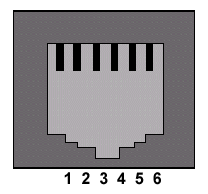
The Prime8 has eight RJ-12 connectors with eight RJ-12 cables to connect to target devices. To add a RJ-12 connection to your hardware, use the pin-out below:

| Prime8 to Target Connections | ||
|---|---|---|
| Prime8 | Target | Pin Description |
| 1 | 6 | Pin B3 on target PIC® MCU or PIC® DSC - C Aware Real-Time Debugging (Optional) |
| 2 | 5 | Pin B6 on target PIC® MCU or PIC® DSC - ICSP™ Clock |
| 3 | 4 | Pin B7 on target PIC® MCU or PIC® DSC - ICSP™ Data |
| 4 | 3 | Ground (GND) |
| 5 | 2 | Power (VDD)
|
| 6 | 1 | MCLR
|
- The Prime8 draws its power from an AC adapter. However, the connection between pin 5 on the Prime8 and pin 2 on the target device should be left intact. One reason for this is because the Prime8 uses this connection to pull up voltage values. Another reason is because the Prime8 is capable of supplying a variable voltage (+2.0V to +5.0V) to the target board. This can be done when using a PC by selecting the "Supply Power" option in CCSLoad and setting the voltage level on the "Settings" tab. When not using a PC, the voltage can be set on the Prime8 by using the menu system.

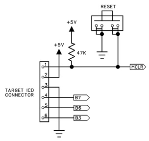
Target ICD Circuit Schematic
- In order to use in-circuit programming, the I/O pins B6 and B7 are reserved on the PIC® MCU or PIC® DSC. Since the Prime8 is not capable of debugging, pins B6 and B7 can be used in the target circuit. If pins B6 and B7 are used in the target circuit, ensure the circuit has high impedance during the programming process. However, some PIC® MCUs or PIC® DSCs do not use pins B6 and B7 for programming. Always check the datasheet to find the proper programming pins. The table below lists some of the PIC® MCUs that use different programming pins.
| Programming Pins | ||
|---|---|---|
| PIC® MCU | Clock Pin | Data Pin |
| PIC12F629 | GP1 | GP0 |
| PIC12F675 | GP1 | GP0 |
| PIC12F683 | GP1 | GP0 |
| PIC16F630 | RA0 | RA1 |
| PIC16F676 | RA0 | RA1 |
| PIC16F684 | RA0 | RA1 |
| PIC16F688 | RA0 | RA1 |
- The MCLR pin is used for programming. While programming, the MCLR pin will have +13V supplied to it, or +5.0V while programming a PIC18J® MCU, PIC24® MCU, or dsPIC® DSC. The 47K resistor to +5.0V is sufficient isolation to protect the PIC® MCU or PIC® DSC from the +13V. However, if anything else is connected to the MCLR pin, be sure the +13V will not damage or interfere with the connected device.
- Since the Prime8 is not capable of debugging, the Prime8 cannot use the monitor feature for debugging. This means that pin B3 can be used in the target circuit since it cannot be used by the monitor feature.
- The Prime8 is not capable of programming using the Low Voltage Programming mode. Programs being written to the target devices should have the NOLVP fuse set.
- If the Prime8 is being used to program a target device, the Prime8 generates a clock signal that is used to program the PIC® MCU or PIC® DSC without the need of a running oscillator.
For additional help connecting the Prime8 to your hardware, contact CCS Technical Support.


