loops0901
Joined: 01 Apr 2012
Posts: 5
Location: Malaysia


|
| Generated PWM |
 Posted: Thu Jun 07, 2012 11:41 am Posted: Thu Jun 07, 2012 11:41 am |
 |
|
Hi,
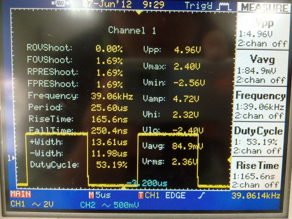
I am using PIC16F877 to generate PWM signal. I found that the generated signal is having Vmax=2.40V and Vmin=-2.56V . The waveform as shown as image below:

Is this normal? As i know, the PWM signal should be from 0V to 5V. But the generated PWM is from -2.56V to 2.40V.
I am using the following code:
| Code: | #include <16F877.h>
#fuses HS, NOWDT, NOPROTECT, BROWNOUT, PUT, NOLVP
#use delay(clock = 20000000)
main()
{
output_low(PIN_C1); // Set CCP2 output low
output_low(PIN_C2); // Set CCP1 output low
setup_ccp1(CCP_PWM); // Configure CCP1 as a PWM
setup_ccp2(CCP_PWM); // Configure CCP2 as a PWM
setup_timer_2(T2_DIV_BY_16, 124, 1); // 500 Hz
set_pwm1_duty(31); // 25% duty cycle on pin C2
set_pwm2_duty(62); // 50% duty cycle on pin C1
while(1);
} |
I am using this generated PWM signal for L298 to control my peltier. Voltage supply is 12V. When i supply 90% duty cycle to L298, the output voltage that i measured for peltier is only equal to 7.8V. I am wondering whether this generated PWM is the factor or not.
Thanks |
|


